06 November 2026
There was a fault which resulted in an error that led to a failure.
I wrote about stack overflows in Playing with FreeRTOS, part I and described it as spooky. Now we're going deeper. What if the fault is not in software design, but in the hardware itself? How do we even describe such problem, does specificity matter?
Let's first go over the terminology. Defect -> fault -> error -> failure. All the way down there's a defect. That is, something went wrong on the physical layer, for example a wire is permanently grounded. Fault is on the logical layer, we'll describe these with a t0/t1 model (stuck-at-0 and stuck-at-1). Error is the manifestation in data, for example wrong value on a wire and to see the result, it has to travel through the sensitive path. More on that later. Failure is when the error leads to the system not accomplishing its task properly.
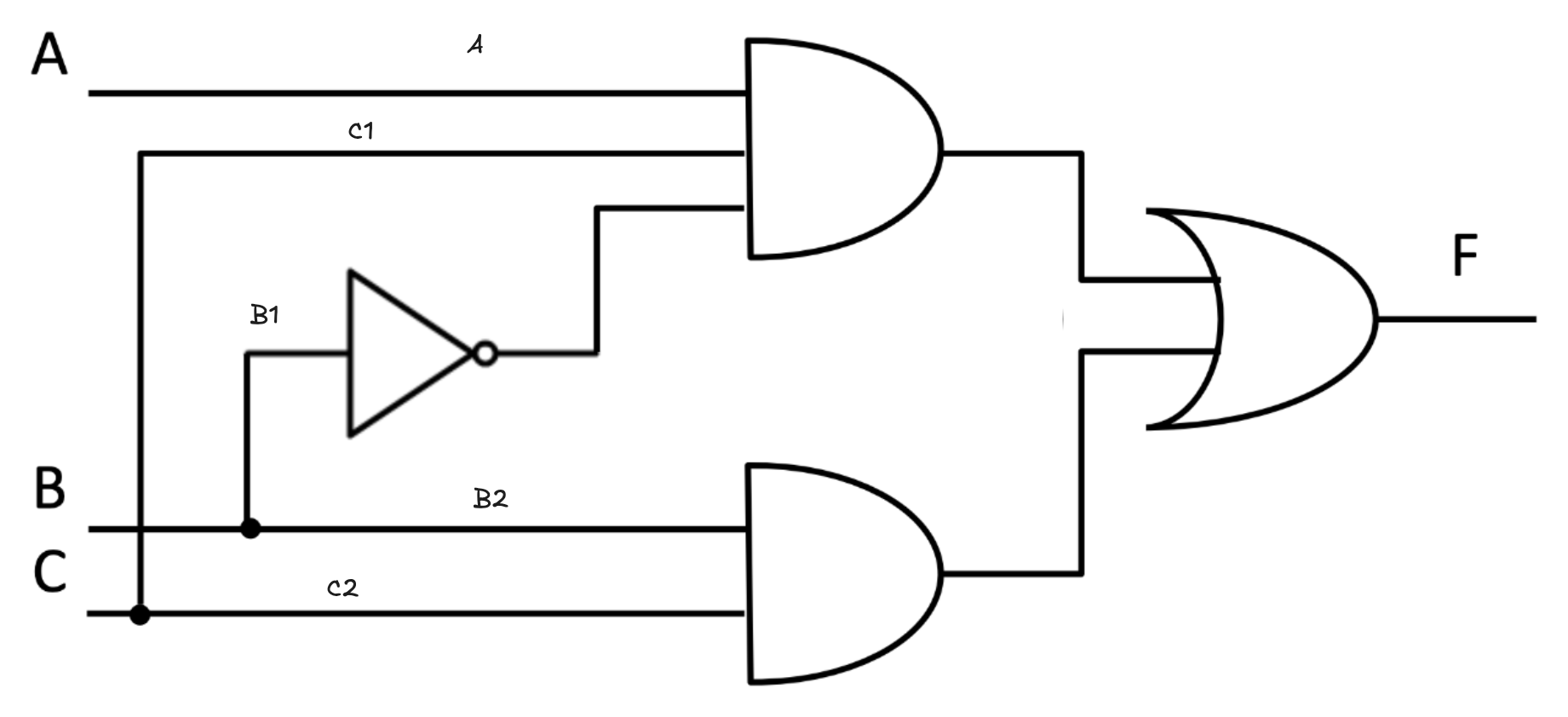
I will mainly talk about faults, because the testability of a system revolves around them. Let's imagine this circuit:
there are three inputs (A,B,C) and one output (F). There are AND gates, an inverter and an OR gate. We would like to test this circuit and determine which faults are detectable in which configurations. We'll do this intuitively, with the use of sensitive paths. A sensitive path is path from the fault to the output along which the fault's effect propagates. We'll sensitize the path, so that nothing blocks this propagation. Let's imagine there being a fault on the A wire, it will be a fault type t0. Meaning, that this wire is permanently grounded.
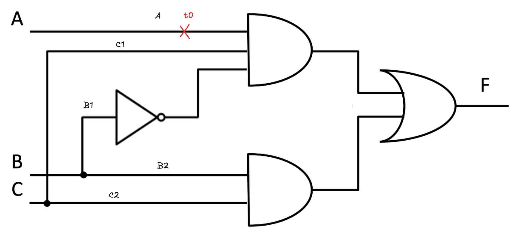
To see any effect, we'll make A be one for this specific scenario, otherwise the fault would not have a chance of affecting anything. Then we'll set the inputs B,C so that A is not blocked. We'll want the bottom AND to be zero, so that the fault on A propagates. We'll set C to 1 and B to 0. In this configuration, without a fault, the output F is 1. However, with the fault the result is zero. So we have detected our first t0 fault!
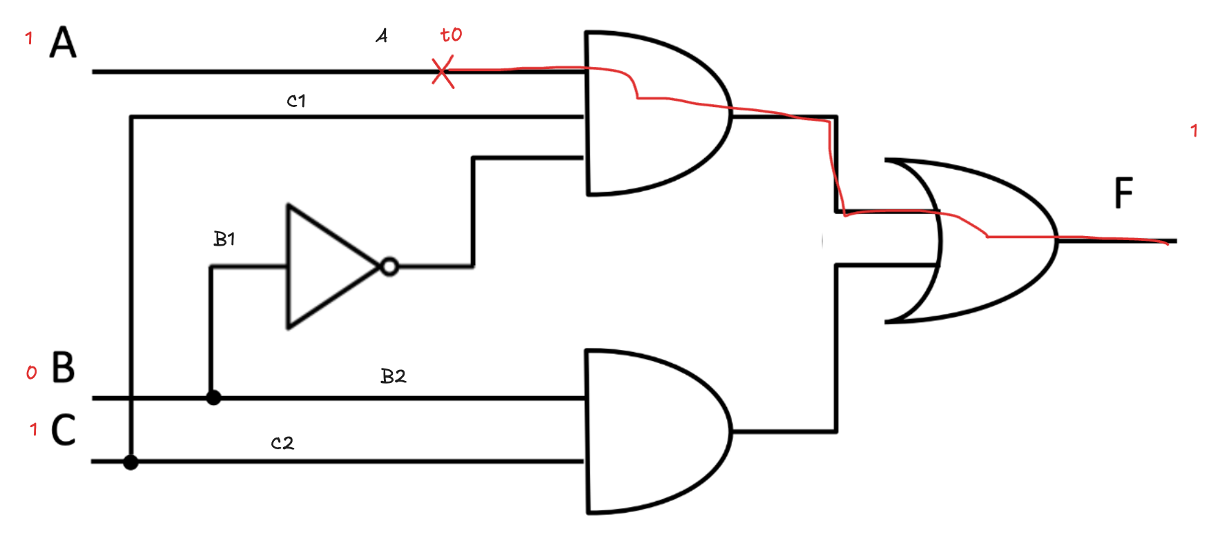
We'll at the same time check, whether there is not another detectable fault for this configuration of inputs. And yes, there are! t0 on C1 affects the result in the same way and t1 on B1 does too. Let's now continue choosing faults on wires and seeing their configurations, checking all the faults this makes detectable. Let's also construct a table. (I apologize to anyone who is color blind and is reading these images, and for not highlighting all sensitive paths.)
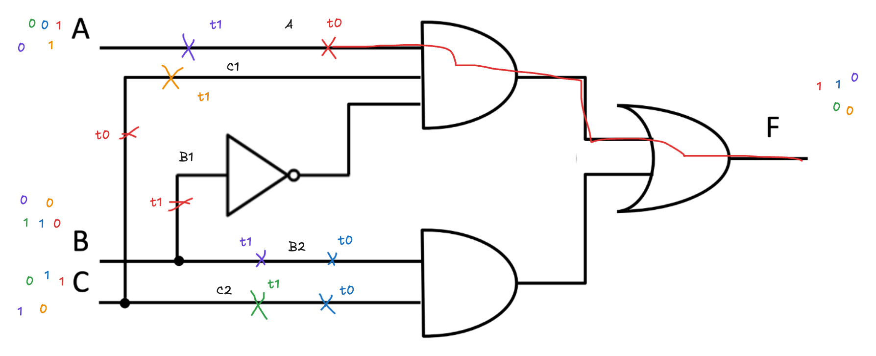

We were able to test both t0 and t1 on every wire, except for B1, where we weren't able to test t0. Let's go over why this is the case and why this fault isn't detectable in this circuit. B1 needs to be 1 to test t0 on it. To be non blocking, A and C need to be 1 too, as to allow the signal to pass through the upper AND on fault. However, if C and B need to be one, that means the lower AND will yield 1, so we'll not be able to detect the fault on B1 for it does not change the output F.